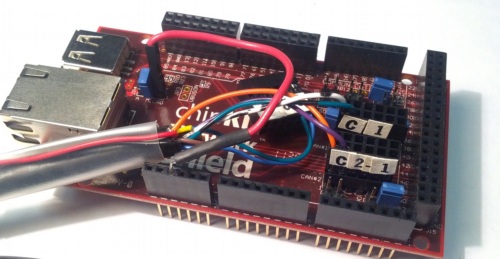
CAN1 plug on the OBD-II cable to the 12-pin header labeled
CAN1 on the Network Shield. Make sure the 2 wires line up with the CANH
and CANL labels on the board as well.CAN2-1 plug on the OBD-II cable to the 12-pin header labeled
CAN2 on the Network Shield.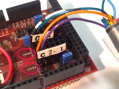
At this point, the reader should be completely functional.
There are a few optional paths at this point:
If you want wireless support, now is the time to add a Bluetooth module. We have setup instructions for the SparkFun BlueSMiRF.
Without an enclosure, the VI is at risk of static shock damage and strain damage in the event of a drop. There are instructions for an optional plastic enclosure
If you want to power the VI from the vehicle, that's possible with some extra wiring.
Otherwise, continue on to final assembly.