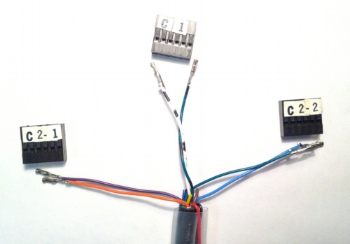
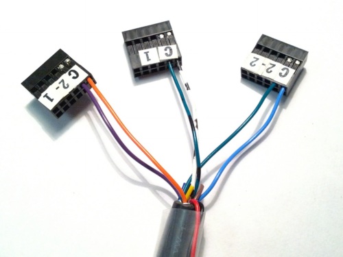
CAN1, CAN2-1 and CAN2-2 wire pairs (see the table
above) to one crimp pin housing each. There should be three crimp housings
with two wires connected to each. The + in pin 1 and - in pin 3 (you'll
see in the schematic below that pins 2 and 4 will also work fine).CAN1, CAN2-1, CAN2-2 and
three -+'s to make sure you get the orientation correct.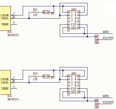
Slide the shrink tubing and center it on the end of the insulation. Bend the red/black power wires and tuck them between the shrink tubing and main cable insulation. Leave the loop accessible to allow us to pull them free in the future. With a heat gun or lighter, shrink the tubing. If you don't have shrink tubing, wrap some electrical tape around the end to keep the loose wires held down.
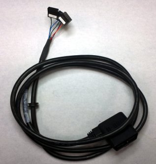
After attaching the crimp housings, add the power jumper.