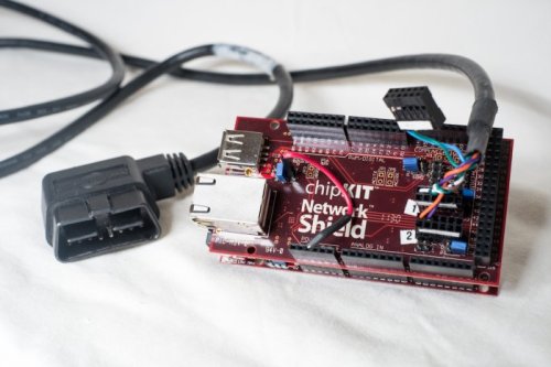
The current implementation uses the Digilent chipKIT Max32, an Arduino-compatible microcontroller based on PIC32. The Network Shield add-on adds two CAN transceivers, which is enough to enable most OpenXC applications.
The translator is powered via its micro-USB port, which is connected to the host device. CAN messages are received via the OBD-II port in the driver's footwell.
If you want wireless support, we have documentation and an extended parts list for adding a Bluetooth module.
This is a list of the hardware used in the reference OpenXC kit - you're guaranteed to have a 100% compatible OpenXC device if you use these parts exactly. There are many equally compatible variations on this list from hundreds of different vendors, so feel free to use other parts you may have on hand (like the crimp connectors, for example).
This is a list of the tools needed to assemble the kit.
For the suggested enclosure, you'll also need the following:
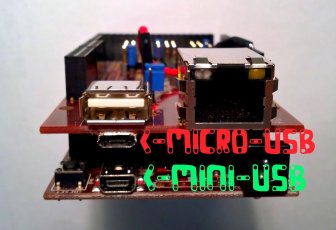
There are 2 USB ports on the combined Max32 and Network Shield, so getting the cables sorted out can be a bit confusing. The ports are meant to be used as follows:
The OBD-II cable is safe to plug in at any time, with the vehicle running or off. The cable only fits one way into the vehicle's port, like a USB cable.
Bought all of the parts for the VI? The detailed assembly guide is next.