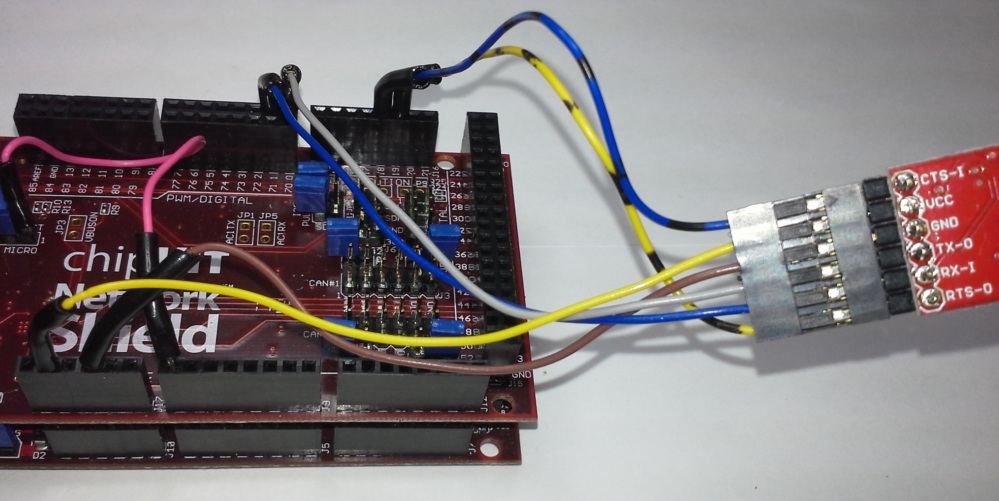
- Solder the 6-pin header strip to the BlueSMiRF breakout board.
- Create 6 3" wires of different colors with a male crimp pin on one end and a
female crimp housing on the other. You may want to wrap the crimp housings in
shrink tubing to avoid shorts.
- Attach the 6 wires to the BlueSMiRF board, and the other ends to the Network
Shield according to the pins defined in the
documentation.
- Find a good place to tuck the Bluetooth module away so the wires aren't
shorting out and it won't get in the way of the enclosure.

Finally, you need to set the baud rate of the BlueSMiRF module to match the
output data rate of the VI. Check in the UART section of the VI firmware
documentation for the correct baud rate for the latest release.
Requirements
- Computer or Android device with Bluetooth support
- If using a computer, a Bluetooth or serial port terminal client
If using an Android device, a Bluetooth terminal app like
BlueTerm
Power up the BlueSMiRF module by giving the chipKIT power - confirm there is
a red light flashing on the BlueSMiRF.
- Pair with the device (look for the FireFly or RN-42 device that has 4
matching characters from the BlueSMiRF's MAC address) from the computer or
Android device
- Open a serial terminal to the connected device
- Send these AT
commands
to set the baud rate to 460800 (replace 460800 with whatever value you found
in the VI firmware documentation)
- Type
$$$ to enter command mode - it should echo back CMD
- Type
SU,46 and press Enter to switch the baud rate to 460800 (the first
2 digits of the baud rate) - it should echo back AOK
- Type
D and press Enter to print out the BlueSMiRF's settings - verify
that the baud rate is set to what you expect it to be.
- Power cycle the BlueSMiRF - you're all set!
Give a test by flashing the OpenXC VI emulator firmware, and if you have
trouble, look at the troubleshooting steps.
