
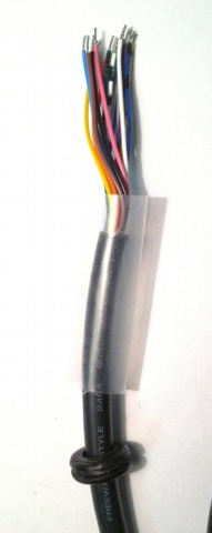
If you plan to use an enclosure, slide the round grommet onto the bare wire end of the cable (you won't be able to do this later without cutting a slit in the grommet). If you don't use the grommet, plan on finding another form of strain relief. Cut a section of 3/8" shrink tubing about 1" long and slide it onto the cable.
Crimp a female pin onto the following wires and verify the connection to the expected pin on the OBD-II connector using a multimeter. The pinout for the cable recommended above is available at OBD2Cables.com.

Take note that the crimp pins need to be squeezed in two places (ideally with a proper crimp tool) - once around the wire end, and once around the insulation.


These instructions describe how to make a 3 bus cable. The chipKIT only has 2
CAN controllers, so you will be using at most 2 of the buses at one time. Most
vehicles use what we will call the CAN1 and CAN2-1 buses.

| Wire Color | OBD-II Pin | Bus | Polarity |
|---|---|---|---|
| White and black | 6 | CAN1 | + |
| Green and black | 14 | CAN1 | - |
| Orange | 3 | CAN2-1 | + |
| Purple | 11 | CAN2-1 | - |
| Light blue | 1 | CAN2-2 | + |
| Green | 8 | CAN2-2 | - |
When all pins are attached, verify that you have good electrical conductivity with the intended pin.

After connecting and testing the crimp pins, trim the red (battery voltage) and black (ground) wires down to the insulation but leave them sticking out of the main cable insulation. If you want to power the chipKIT from the vehicle in the future, you'll need these wires.
Trim all of the other uncrimped wires down to the main cable insulation - we won't be needing them.
Once you've built the OBD-II cable, attach the crimp housings.